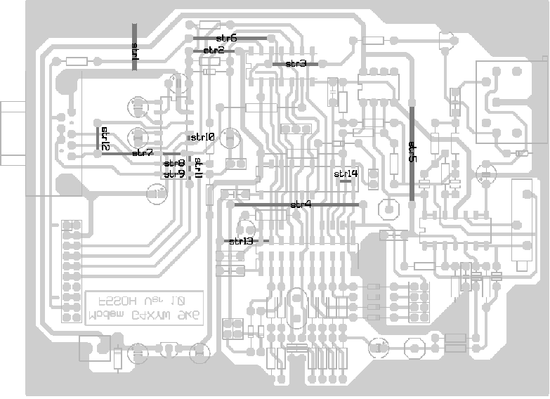
|
List of components
|
|
Value
|
Reference
|
Config
|
Remarks
|
| AT90S1200 |
IC1
|
|
(shifted of one 1/2 case with
IC5 in full-duplex)
|
| 74HCT14 |
IC2
|
|
|
| LM393 |
IC3
|
|
|
| CA324 |
IC4
|
|
|
| AT90S1200 |
IC5
|
Full
|
Only in Full-duplex
|
| MAX232 |
IC6
|
ASY
|
Only on port series (ASY)
|
| 78L05
/ 7805 |
IC7
|
|
Regulator 5v
|
| 9.8304MHZ |
X1
|
|
|
| NPN |
TR1
|
|
|
|
Jumpers
|
| L1 |
L1
|
|
Jumper: CW ON/OFF
|
| L2 |
L2
|
Full
|
Jumper: Tx PLL ON/OFF (sending
Clock Tx in Full-duplex)
|
| L3 |
L3
|
|
Jumper: mode ASY (max232)
|
| L4 |
L4
|
|
Jumper: Tx mode (see back)
|
| L5 |
L5
|
|
Jumper: Tx mode (see back)
|
| L6 |
L6
|
Full
|
Jumper: invert Clock Tx (full)
|
| L7 |
L7
|
|
disable watchdog
|
| L9-10 |
L9-10
|
|
Jumper: invert DCD
|
| L11 |
L11
|
Full
|
Jumper: invert Clock Rx (full)
|
| |
|
L4
|
L5
|
Mode
|
|
Not
|
Not
|
Raised cosine (default)
|
|
Not
|
Yes
|
GMSK
|
|
Yes
|
Not
|
sinx/x compensated cosine
|
|
Yes
|
Yes
|
Raised cosine (default)
|
|
| T1 |
T1
|
|
Test Rx eyes
|
| T4 |
T4
|
|
Test Tx eyes
|
|
| LED |
DCD1
|
|
Led Dcd
|
| 4µ7 |
C1
|
|
Radial chemical condenser
|
| 18pF |
C2
|
|
Ceramic condenser 2,54
|
| 18pF |
C3
|
|
Ceramic condenser 2,54
|
| 1µF |
C4
|
|
Radial chemical condenser
|
| 100nF |
C6
|
|
Condenser polyester
|
| 220pF |
C7
|
|
Ceramic condenser 5,08
|
| 100pF |
C8
|
|
Ceramic condenser 5,08
|
| 10µF |
C9
|
|
Radial chemical condenser
|
| 220pF |
C10
|
|
Ceramic condenser 5,08
|
| 470pF |
C11
|
|
Ceramic condenser 5,08
|
| 100nF |
C12
|
|
Condenser polyester
|
| 100nF |
C13
|
|
Condenser polyester
|
| 10µF |
C14
|
|
Radial chemical condenser
|
| 1µF |
C15
|
|
Radial chemical condenser
|
| 100nF |
C17
|
|
Condenser polyester
|
| 100nF |
C18
|
|
Condenser polyester
|
| 100nF |
C19
|
|
Condenser polyester
|
| 10µF |
C31
|
ASY
|
Radial chemical condenser
|
| 10µF |
C32
|
ASY
|
Radial chemical condenser
|
| 10µF |
C33
|
ASY
|
Radial chemical condenser
|
|
| 1N4148 |
D1
|
|
Diode
|
| 1N4148 |
D2
|
|
Diode
|
| 1N4148 |
D3
|
|
Diode
|
| 1N4148 |
D4
|
|
Diode
|
| 1N4148 |
D5
|
|
Diode
|
| 1N4148 |
D6
|
|
Diode
|
| 1N4148 |
D7
|
|
Diode
|
| 1N4148 |
D8
|
Full
|
Diode
|
| 1N4007 |
D9
|
|
Diode of protection (optional)
|
| DZ33V |
D10
|
|
Diode Zener 33Volts (optional)
|
|
| 2K2 |
R1
|
|
Resistance 1/4 W
|
| 3M3 |
R2
|
|
Resistance 1/4 W
|
| 470 |
R3
|
|
Resistance 1/4 W
|
| 680 |
R4
|
|
Resistance 1/4 W
|
| 470 |
R5
|
|
Resistance 1/4 W
|
| 2K2 |
R6
|
|
Resistance 1/4 W
|
| 10K |
R7
|
|
Resistance 1/4 W
|
| 10K |
R8
|
|
Resistance 1/4 W
|
| 10K |
R9
|
|
Resistance 1/4 W
|
| 10K |
R10
|
|
Resistance 1/4 W
|
| 10K |
R11
|
|
Resistance 1/4 W
|
| 10K |
R12
|
|
Resistance 1/4 W
|
| 10K |
R13
|
|
Resistance 1/4 W
|
| 10K |
R14
|
|
Resistance 1/4 W
|
| 5K1 |
R15
|
|
Resistance 1/4 W
|
| 5K1 |
R16
|
|
Resistance 1/4 W
|
| 10K |
R17
|
|
Resistance 1/4 W
|
| 5K1 |
R18
|
|
Resistance 1/4 W
|
| 5K1 |
R19
|
|
Resistance 1/4 W
|
| 10K |
R20
|
|
Resistance 1/4 W
|
| 1M |
R21
|
|
Resistance 1/4 W
|
| 560 |
R22
|
|
Resistance 1/4 W
|
| 100K |
R23
|
|
Resistance 1/4 W
|
| 100K |
R24
|
|
Resistance 1/4 W
|
| 100K |
R26
|
|
Resistance 1/4 W
|
| 56K |
R25
|
|
Resistance 1/4 W
|
| 100K |
R27
|
|
Resistance 1/4 W
|
| 10K |
R28
|
|
Resistance 1/4 W
|
| 10K |
R29
|
|
Resistance 1/4 W
|
| 220K |
R30
|
|
Resistance 1/4 W
|
| 39K |
R31
|
|
Resistance 1/4 W
|
| 82K |
R32
|
|
Resistance 1/4 W
|
| 470 |
R33
|
|
Resistance 1/4 W
|
| 10KLIN |
RV1
|
|
Adjustable multi-turn horizontal
|
|
| 12V |
ALIM1
|
|
Connector alim 12V
|
| SCC |
SK2
|
|
Connector DB9-Female
|
| SK1 |
SK1
|
TNC
|
Connector Tnc
|
| TRX |
SK3
|
|
Base DIN 5pin/180°
|


